Almost always, the emphasis about the railroads and model railroading in general is about the roadbed, track, rails, turnouts, passing sidings, etc. likely because that is the largest capital expense for a company and maintance costs as well as the most visible. Almost not attention is given to those poles that parallel the right of way, but casual mentions here and there. But just like wiring your layout with DC current, those wires carried DC and I am talking about pre-modern day technology of telephones and CTC. While it was not impossible to operate safely without the benefit of DC, come to find out there was a good amount of redundancy built into the system.
Railroad telegraph systems were surprisingly robust for their time. They look like a single line of poles stretching into the distance,
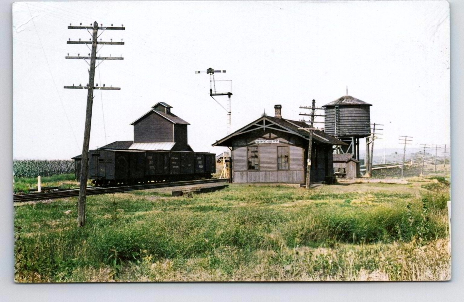
but behind that simplicity was a fair amount of built-in redundancy and operational backup. What follows are my comments and understanding on how it worked.
How Redundancy Worked in Railroad Telegraph Systems
1. Multiple Wires on the Same Pole
Most railroad telegraph poles carried several parallel wires, not just one. These served different purposes:
- Primary dispatch wire for train orders
- Secondary or “way” wires for stations and maintenance
- Commercial telegraph company wires (Western Union often leased space)
- Spare wires kept unused but ready to be connected
If one wire failed, dispatchers could switch to another circuit with minimal delay.
2. Sectionalized Circuits
Railroads divided their telegraph lines into sections. If a wire broke or shorted in one section:
- Operators could cut that section out
- Traffic could be rerouted through adjacent sections
- Repairs could be isolated without shutting down the entire line
3. Ground Return as Backup
Telegraph circuits could operate in two modes:
- Metallic circuit (two wires)
- Earth return (one wire + ground)
If one conductor failed, the system could fall back to earth return, which was less ideal but kept communication alive.
4. Local Batteries at Stations
Each station had its own battery supply for sending messages. If the main line power failed, stations could still:
- Send emergency messages
- Receive train orders
- Communicate with nearby stations
This decentralized power source added resilience.
5. Human Redundancy: Operators and Procedures
Railroads built redundancy into their operational rules, not just the hardware.
If telegraph communication failed:
- Trains reverted to timetable-and-train-order rules
- Flagmen protected trains manually
- Dispatchers issued written orders carried by messengers or train crews
- Block systems could be run in manual mode
This ensured trains could still run safely, though more slowly.
6. Physical Redundancy: Parallel Rights-of-Way
On busy lines, especially in the 20th century, railroads sometimes had:
- Multiple pole lines
- Separate telegraph and telephone circuits
- Microwave towers (later years)
This created layers of backup as technology evolved.
In Short
Yes—railroad telegraph systems were designed with multiple layers of redundancy, both electrical and procedural. The railroads depended on reliable communication for safety, so they engineered the system to survive wire breaks, storms, equipment failures, and human error.
So for the curious among us, were telephone circuits also on these poles?
The answer is yes! Telephone circuits were carried on those same pole lines, and over time they became just as important as the telegraph wires they shared space with. What’s interesting is how the two technologies coexisted and how railroads adapted the pole lines to handle voice communication, which is far more demanding than Morse.
By the early 1900s, most major railroads began stringing telephone circuits on the same pole lines that originally carried only telegraph wires. These circuits supported:
- Dispatcher-to-station voice communication
- Wayside phone boxes for train crews
- Maintenance-of-way communication
- Later, centralized traffic control (CTC) circuits
- Internal railroad business calls
Telephones didn’t replace telegraph immediately, but they ran in parallel for decades.
Telegraph circuits tolerate noise; telephone circuits do not. So railroads upgraded pole lines to support voice:
- Heavier gauge wire
- Better insulators
- Transposition brackets to reduce crosstalk
- Metallic (two‑wire) circuits instead of earth return
- Loading coils on long-distance lines
These improvements made the pole lines look more complex over time.
What follows is a small table depicting Wire Type and Purpose:
|
Wire Type |
Purpose |
| Telegraph | Train orders, Morse traffic |
| Telephone | Voice dispatching, maintenance |
| Signal circuits | Block signals, interlocking |
| Commercial telegraph/telephone | Western Union, Bell System |
| Spare Wires | For emergencies or future expansion |
Railroads often leased space to Western Union or AT&T, so the pole lines became multi-purpose communication corridors.
Telephone circuits added new layers of backup:
- Parallel voice circuits for dispatching
- Separate “talk” and “order” lines
- Emergency telephones in trackside booths
- Fallback to telegraph if voice failed
- Later, microwave and buried cable as additional redundancy
By the mid-20th century, railroads had some of the most robust private communication networks in the country.
By the 1960s–1980s, pole lines were gradually replaced by:
- Microwave towers
- Coaxial cable
- Fiber optics
- Radio (VHF railroad band)
Today, the old pole lines are mostly gone, but they were the backbone of railroad communication for over a century.
Personal Experience
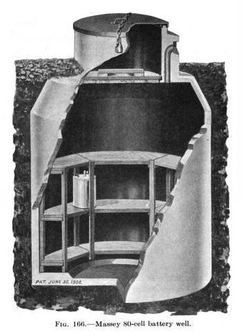
When I was in my high school years observing the Chicago Great Western that ran through Elizabeth, Illinois including the nearby Winston Tunnel, I came across an interesting piece of facilities infrastructure and hardware. So west just outside of Elizabeth, Illinois where the Chicago Great Western Railroad crossed the road at 3937 S. Pleasant HIll Road, on the left side of the track immediately west of the road was a underground concrete bunker. It had a steel rung ladder so you could get down inside this pit. On shelves were large glass battery jars.
What would those have been used for? DC?
This would have been a clue, what I found there fits a very recognizable pattern in early–mid-20th-century railroad communications. Large glass battery jars almost certainly wasn’t for signals or train control at that location even though at the road crossing was the cross buck with flashing lights and bell ringers — it was most likely part of the railroad’s telegraph/telephone power system, specifically a line battery or booster battery installation. Seemed like a remote place to have found this hardware.
Railroad communication circuits — especially long-distance telegraph and early telephone lines — required a stable, constant DC voltage. Because the lines could run dozens or hundreds of miles, the voltage had to be maintained at intervals.
Those big glass jars held wet-cell batteries (often lead-acid or nickel-iron). They provided:
- Line voltage for Morse telegraph circuits
- Power for telephone repeaters or amplifiers
- Power for wayside communication equipment
- Stabilization of long metallic circuits
These were called line batteries, booster batteries, or repeater station batteries.
Railroads often built small concrete huts or bunkers to house:
- Batteries
- Line relays
- Repeater coils
- Lightning arrestors
- Terminal boards
- Junctions between multiple pole-line circuits
Concrete was cheap, fireproof, and protected the equipment from weather and vandalism.
The Chicago Great Western, like many railroads, had these battery shalters at intervals along the line where circuits needed boosting or where multiple wires were joined or rerouted.
The classic Edison-style or lead-acid wet cells were kept in glass jars so operators could:
- See electrolyte levels
- Inspect plates for sulfation
- Maintain them with distilled water
- Replace cells individually
These jars were heavy, durable, and could last decades with proper care.
That spot near Elizabeth, Illinois, makes sense for a few reasons:
- It was a remote stretch where the railroad needed a line battery point to maintain voltage on long circuits between stations.
- It may have been a junction where multiple telegraph/telephone circuits branched or were sectionalized.
- It could have supported dispatch telephone circuits, which required more stable power than telegraph lines.
- The CGW often placed these bunkers near road crossings for easier access by linemen.
Even if there was no station or signal installation nearby, the communications circuits still needed periodic power injection.
In conclusion, a concrete bunker was almost certainly a line battery or repeater hut for the Chicago Great Western’s telegraph and telephone circuits. The glass battery jars provided the steady DC power needed to keep long-distance communication circuits functioning reliably. Sometimes partially buried or bermed for temperature stability, they were built to be fireproof, weatherproof, and vandal-resistant. But the one I climbed down into had the heavy lid off to the side and was obviously no longer in use as the Chicago North Western abandon the CGW line yet the batery jars were still intact at the time I visited the bunker.
APPENDIX
Here’s what you would typically see inside, based on engineering manuals from the 1910s–1950s:
A. Battery Racks
Usually wooden or steel shelving holding:
- Rows of glass battery jars
- Each jar containing a single wet cell
- 16–60 cells depending on the voltage needed
The jars were often arranged in two or three tiers.
B. Terminal Boards
Mounted on the wall:
- Porcelain or slate panels
- Binding posts for each wire
- Lightning arrestors
- Fuses or cut-outs
- Line test points
C. Repeater or Booster Equipment
Depending on the era:
- Telegraph relays
- Repeating sounders
- Line equalizers
- Loading coils (for telephone circuits)
- Induction coils
D. Power Conditioning
If commercial power was available (not always):
- A small rectifier
- Charging panel for the batteries
If not, the batteries were “primary” and replaced periodically.