
Description
For Sale: All Nation’s Weaver Chain Drive Spring Loaded Tensioner Replacement Kit O Scale PN#517ANK
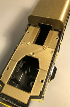
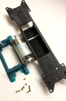
NOTE: Before you purchase, know that you may have to cut a small notch in the floor to easily install as per our instructions below since this product is significantly more robust in dimension to contain the bearing housing. Alternatively, mounting the stand-off to the gear box first and then placing the floor is more difficult to finish the installation, but it can be done. If making modifications to the floor is not for you, then on 2nd thought this kit may not be for you.
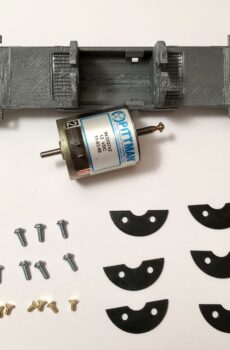
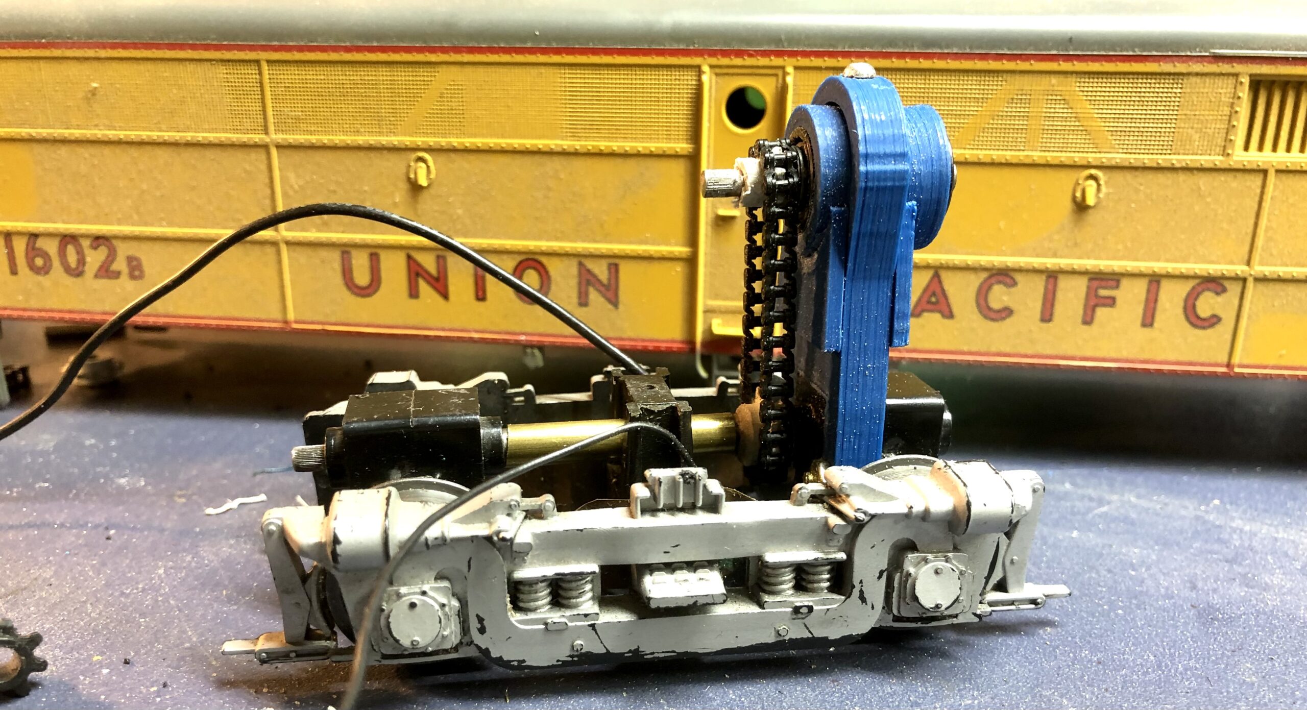
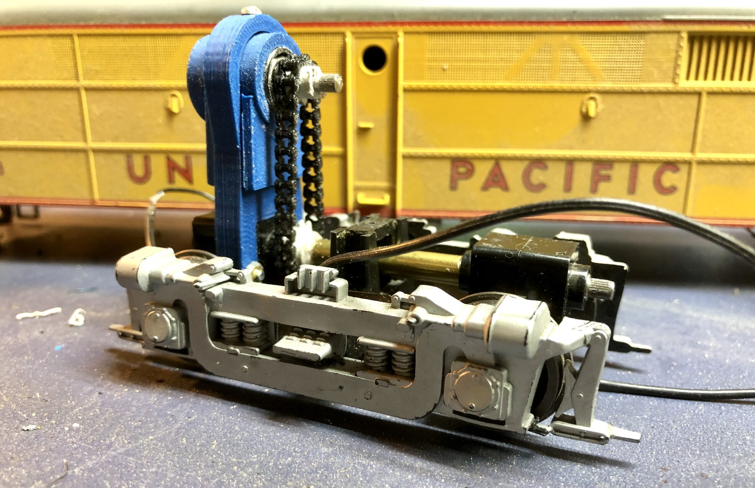
There are many older or dated diesel engine models from Weaver in the field on layouts that over time have drives that give trouble or are not operational. Such was the case with a pair of Union Pacific FA-2 A & B units that ran for many years on my Grandfathers layout. The sprockets cracked or were slipping on the drive shafts and of course the engine did not run.
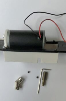
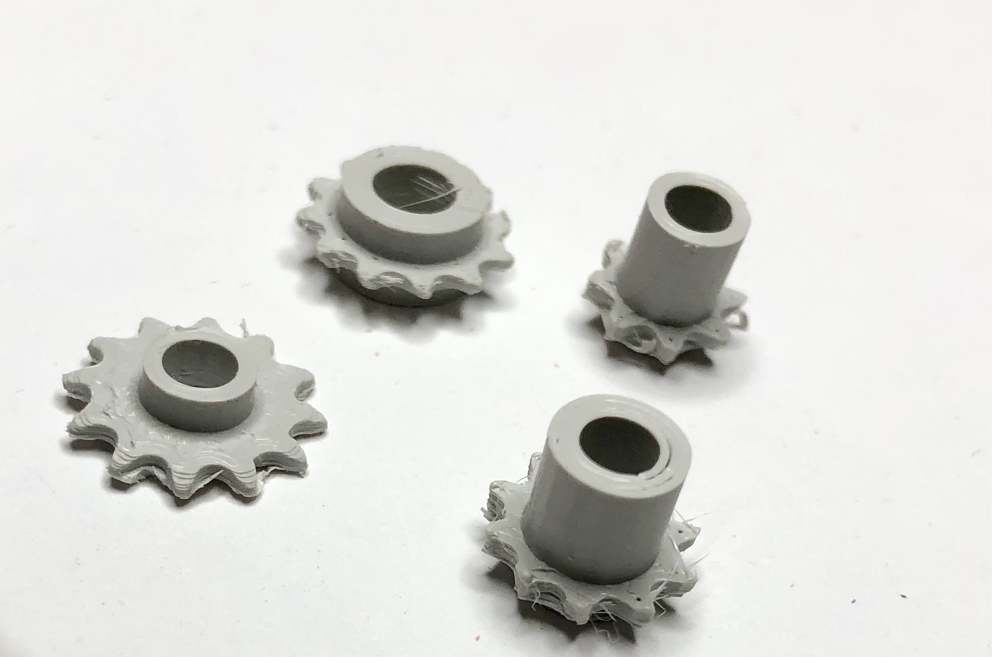
Thus, I started out to 3D print the replacement sprockets in Polycarbonate and fitted them on to the shafts. Well, like any project I tackle, a small job turns into a larger more involved effort, and one thing leads to another. Upon fitting the sprockets, the transmissions had other problems including the gear box housing the worm and worm gear on the axle.
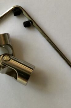
The upper drive shaft was rather sloppy in two ways. First, there was too much horizontal motions, implying that some shim rings were in order since the ladder chain alignment for the top and bottom sprockets was not very satisfactory. There was a potential to break a chain link. Second, there are no formal bearings in the original implementation, just a steel drive shaft, turning on the plastic sleeve that accommodated the drive shaft and given that the connection coming from the motor was a universal slip joint, there was plenty of room, or perhaps too much room, for play in the operation of the mechanism.
Consequently, this kit came about to remedy the situation. Often times, chain drive configurations present a problem that often confronts us with the tension of the ladder chain once installed. It is either too slack or it is too short, and adding a link makes it slack and may cause issues with forward and reversing directions.
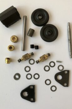
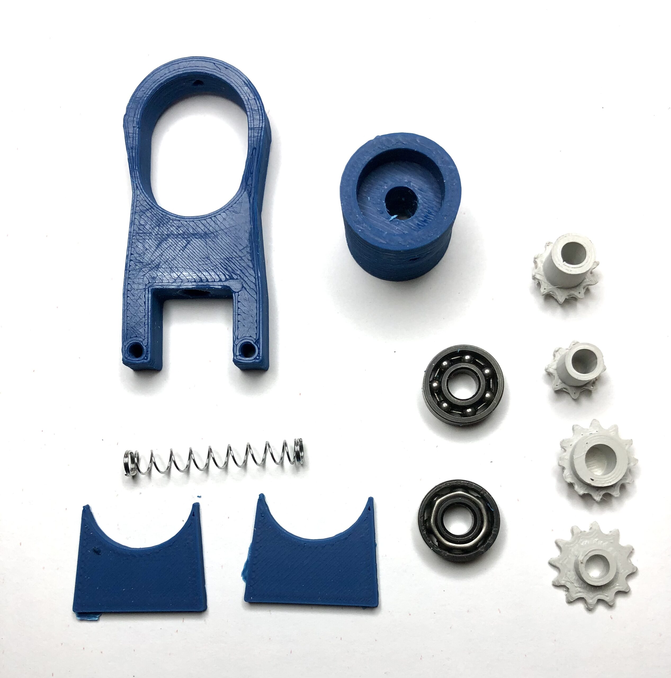
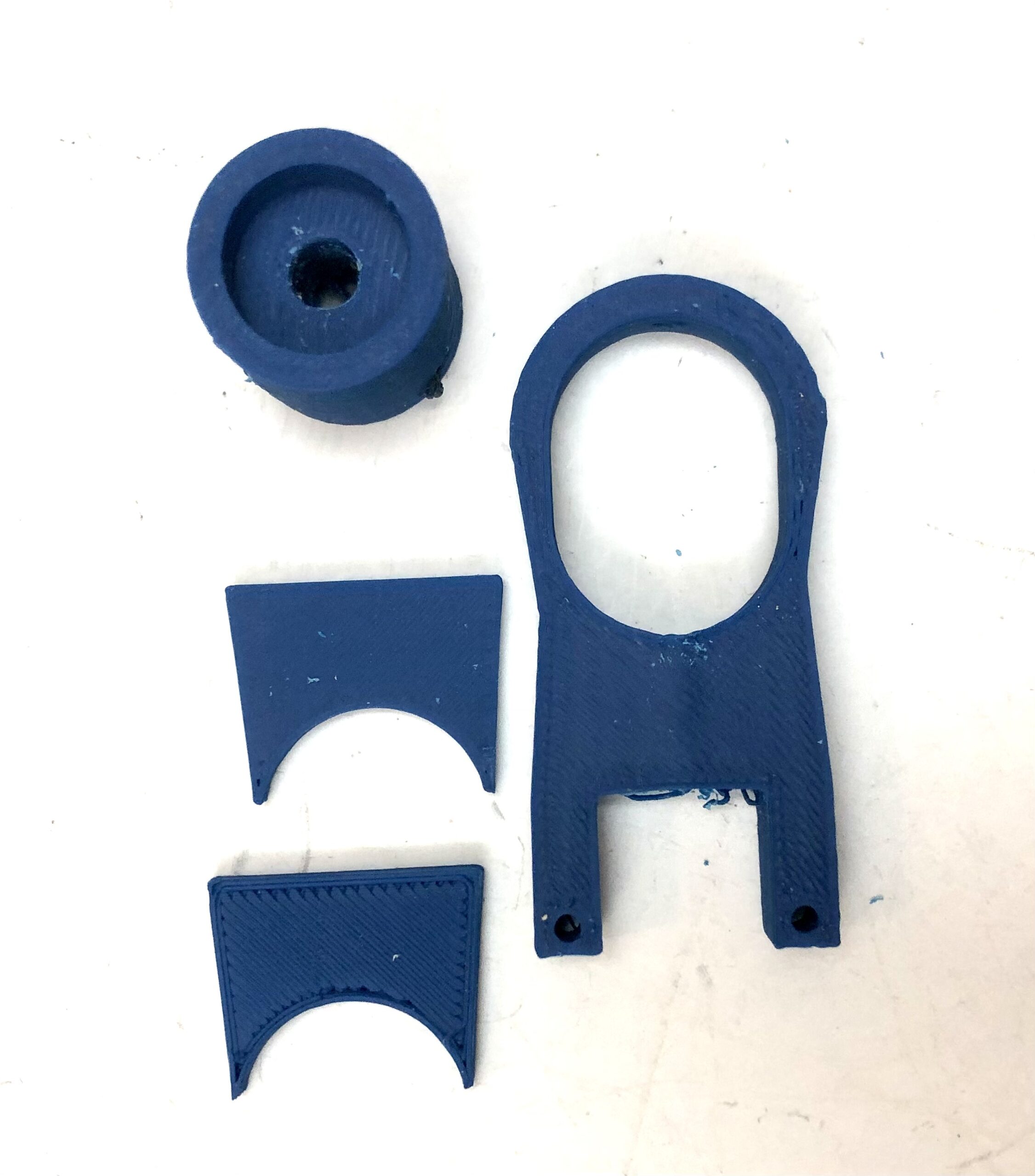
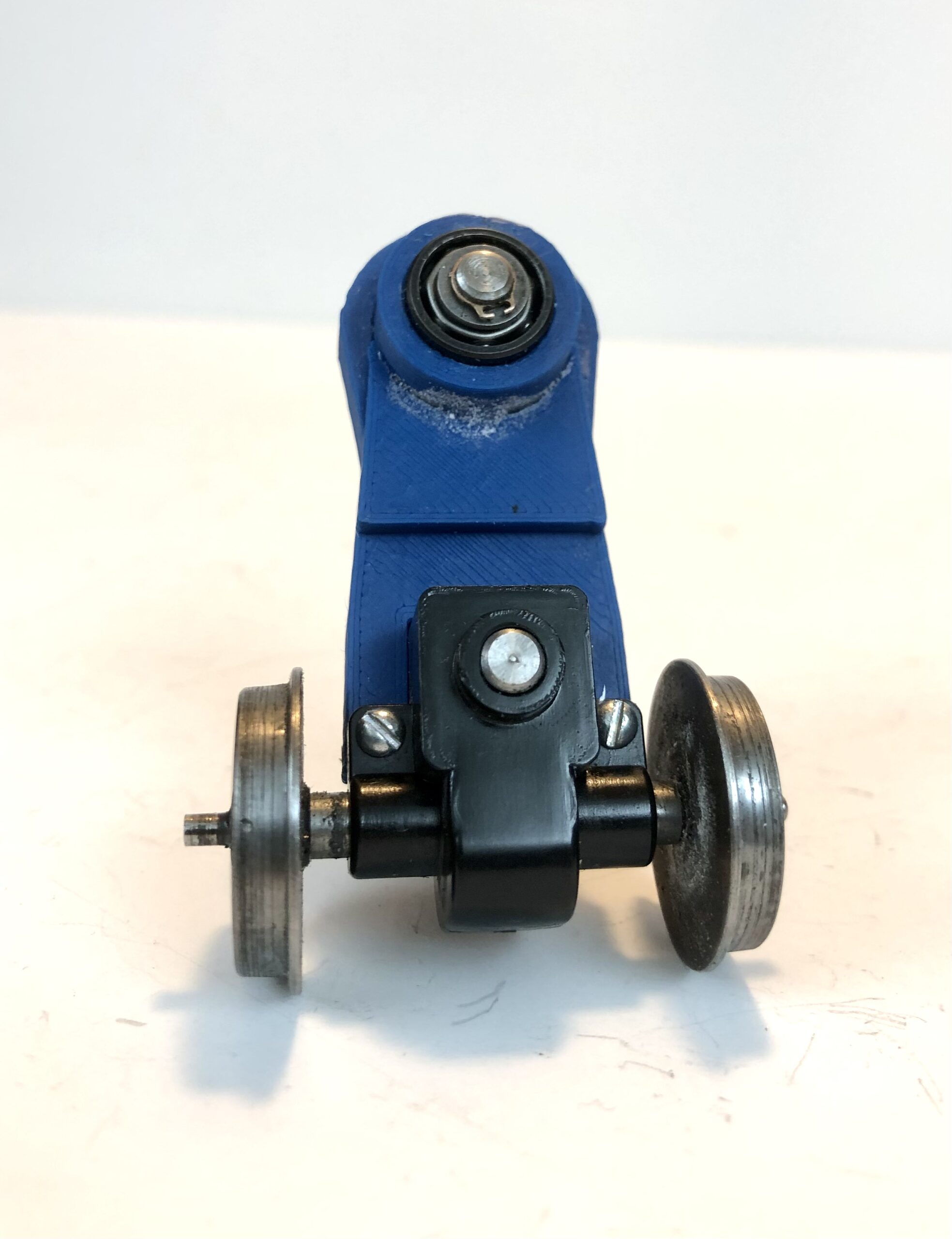
The replacement comes in 3 basic, separately 3D Printed parts with a bit of additional engineering to make this a more precise installation.
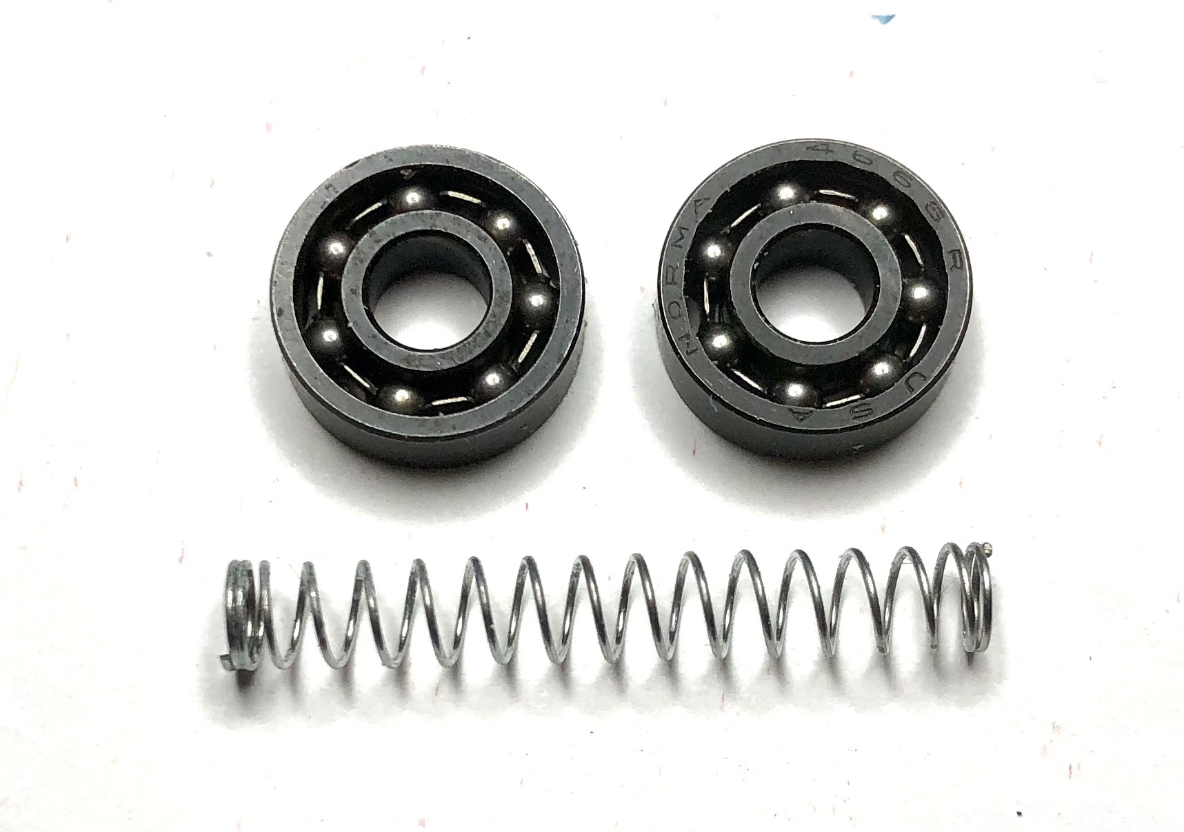
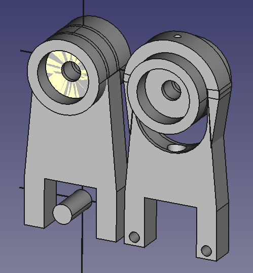
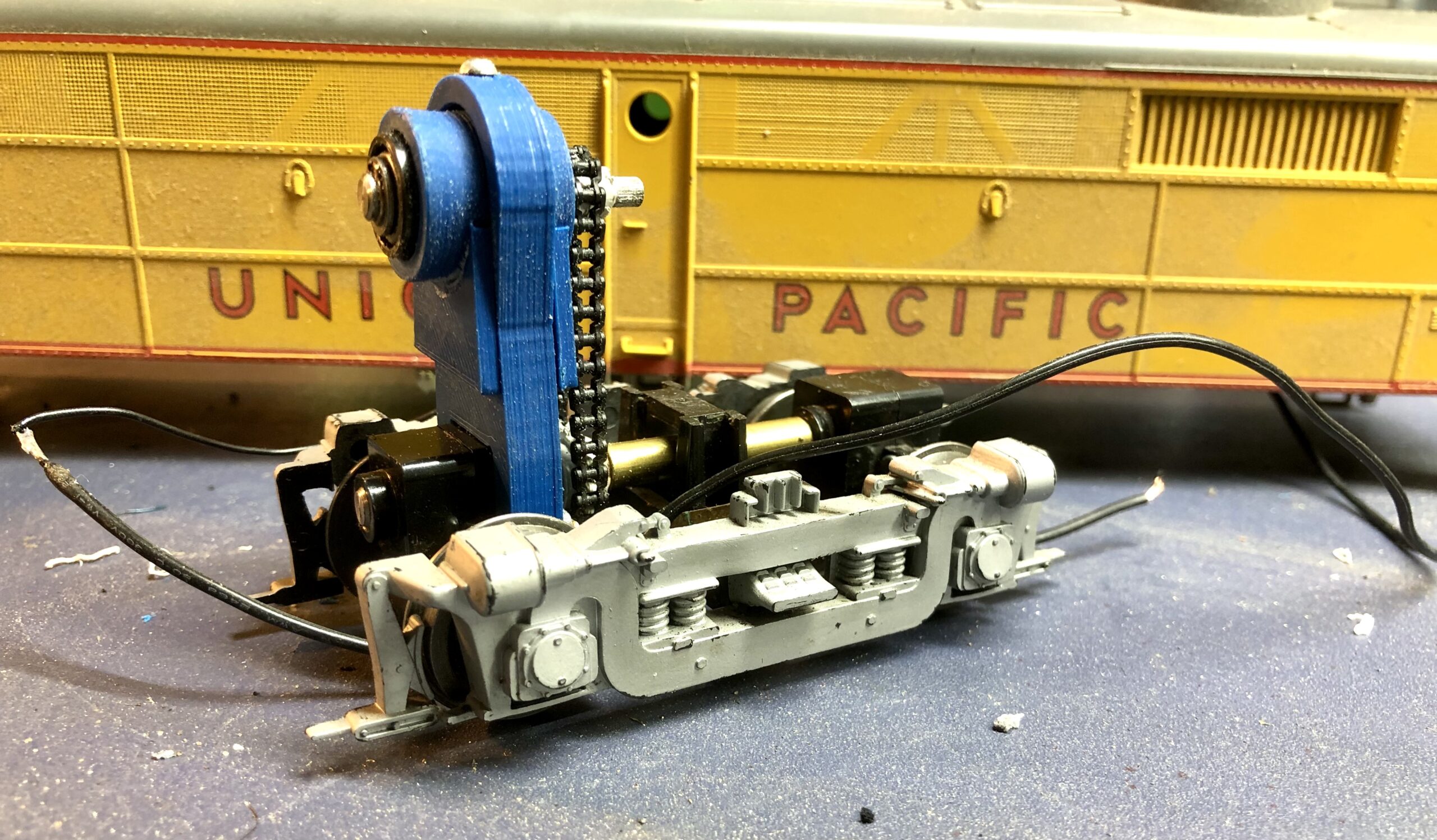
Part 1 is the drive shaft barrel to house the original 3/16″ diameter drive shaft with 2 heavy duty ball bearings, one on the front and the other on the back to support the shaft.
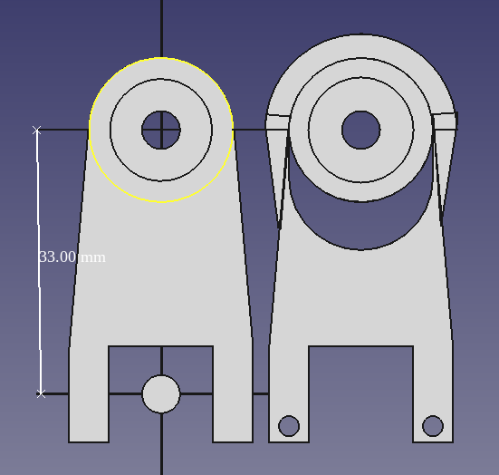
Part 2 is the standoff, a semi-equivalent of the original that mounts with 2 screws to the gear box housing. The big difference is, a printed solid piece that contains the loaded spring that is essentially the same type of spring found in a ball point pen. The standoff is an elongated loop to house Part 1 allowing for the up and down motion as the spring seats into the bottom of the bearing housing. This implementation makes it easier to install the chain allowing for the vertical adjustment.
Part 3, 2 face plates or guide sides that glue to the bottom of Part 1 on both sides such that they slide against Part 2 maintaining the horizontal position of part 1 in the vertical movement. These 4 parts are printed in ABS. Part 1 can be depressed slightly to install the chain and released so that the spring keeps adequate tension to remove an slack.
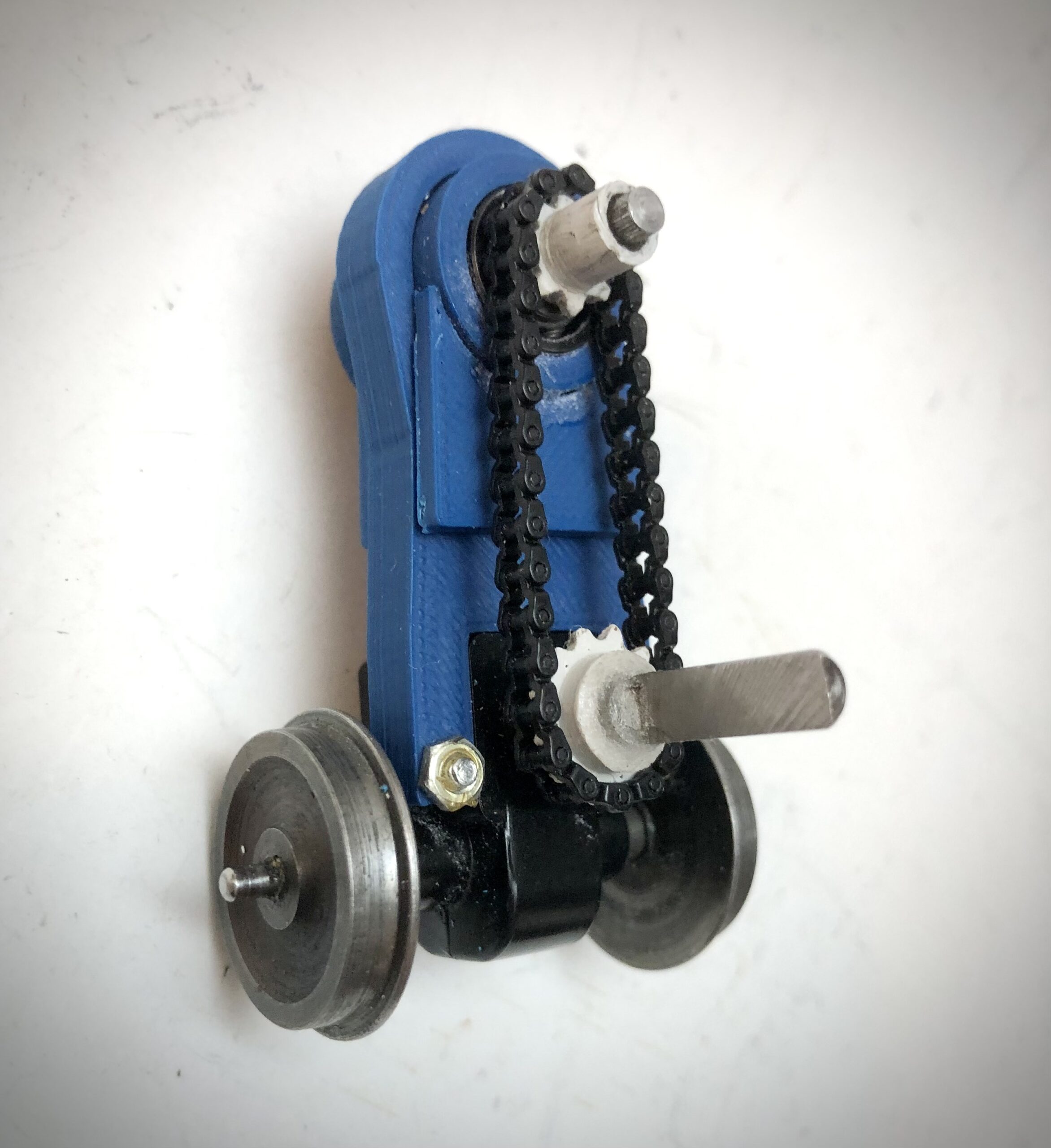
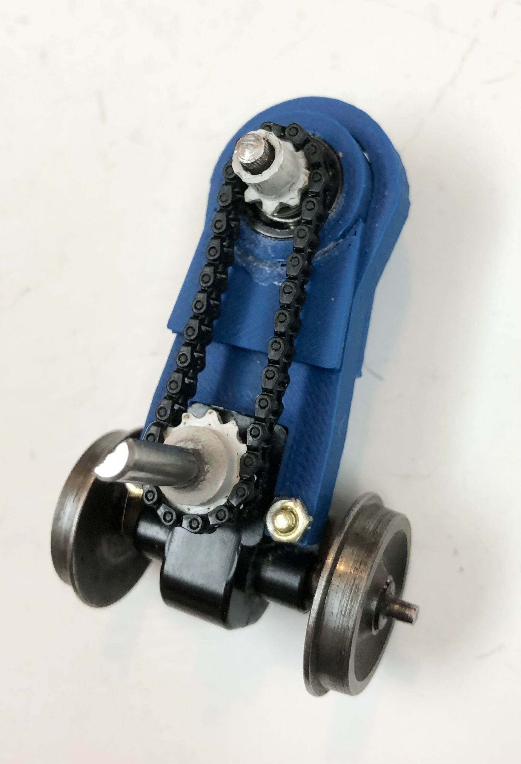
The peak or highest position is set so that the vertical center distance of the top and bottom drive shaft is 33mm and the original chain measures 4″ long when laid out linear on the bench. The original sprockets were 8 teeth on the top and 12 on the bottom. Now those can be changed if one wants a 1:1 ratio we include 12 tooth sprockets top and bottom or a 10 tooth sprocket for the top. Note that the diameter of the bottom drive shaft is larger than the top. Obviously, if one goes with different sprockets, the length of the chain will vary.
When installing the replacement, the top of the loop on Part 2 has a small hole as well as the bearing housing for alignment purposes. However, the modeler may elect to use a 0-90 for alignment and an 0-80 or 2-56 screw, tap the bearing housing not only for alignment but also for securing it once it naturally takes up the correct tension on the chain. If desired, a stronger spring may be substituted or the spring can be further compress by plugging the hole from the bottom forcing it against the bearing housing with more compression. The vertical travel allowed by the spring is about 6mm and ideally on my model I removed 1 link in the chain and used the 2-56 screw to draw it ever so slightly taut.
All 3D printed parts may come with printer plate build material and brims that will need to removed and any thread cleaned up with a file. With the right size triangle file, the teeth can even be burnished. The inside diameter of the holes on the sprockets are slightly under size so that they can be touched up with a file and hand fitted to the upper shaft with the knurl. The bottom shaft does not have a knurl, so one can force press it on, risking stress that may crack it. However, I recommend touching it up with the round file so that you have a tight press on and then applying a little CA with baking power around the hub joint. Always degrease the shaft before gluing.
The upper bearing housing will require the removal of the build support material from one end and cleaning it out, removing any threads. The ball bearing should press fit into the housing without the need to remove any inside diameter material on the housing and will not require any glue. Prior to inserting the drive shaft through the bearings, make sure there are no burs on the drive shaft. In fact, it does not hurt to polish the shaft with some emery paper or fine wet and dry sand paper with oil. There is no need to remove the retainer clip on the end of the shaft when disassembling the old parts. The drive shaft should fit concentrically through both bearings. Before mounting into Part 2, use a little drop of oil from the top of the loop and on each face, turning it by hand. It should feel pretty tight initially. In my case, I mount it into my little hand power drill and run it in both directions for a minute or two, and it should smooth right out.
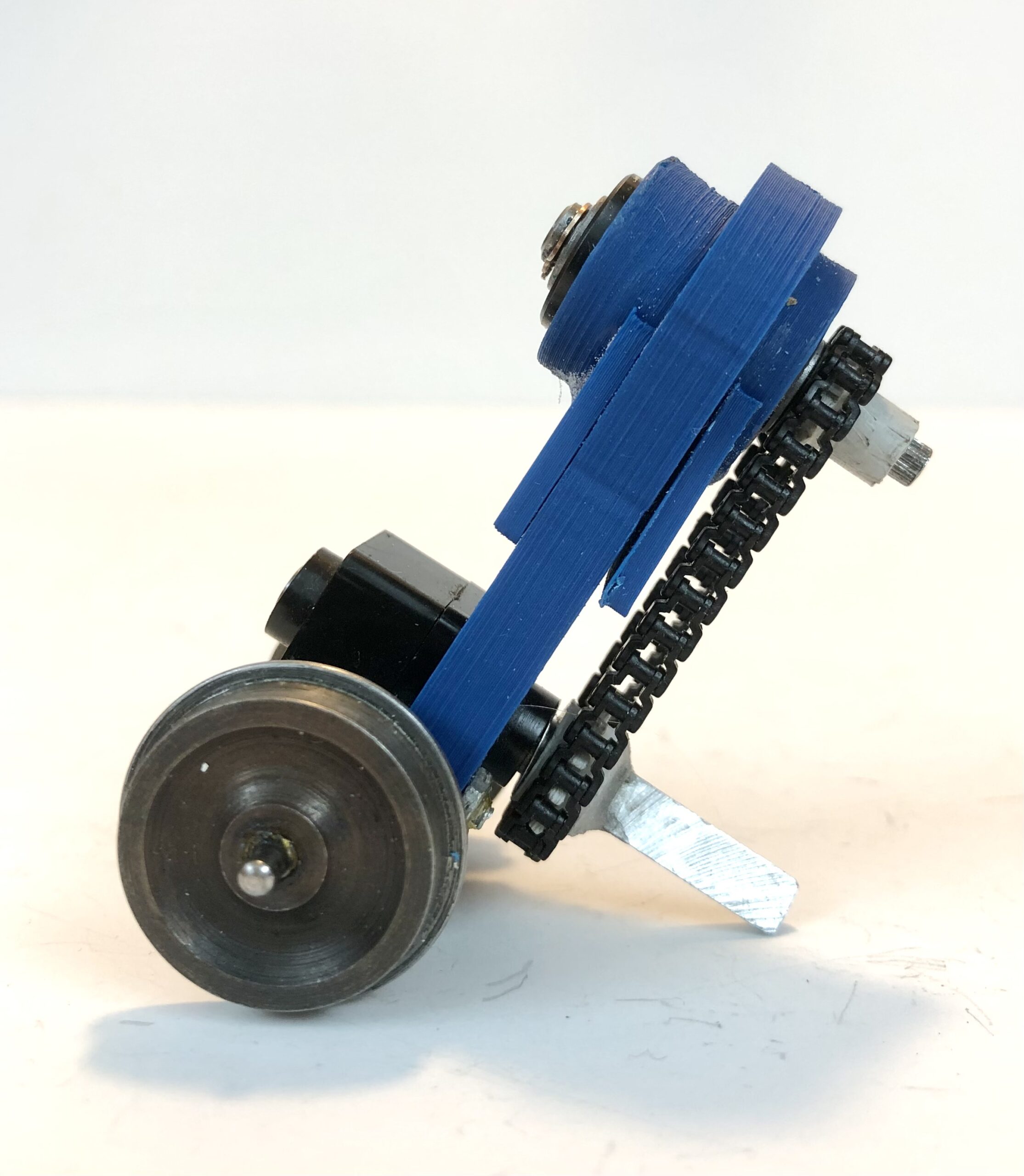
Once assembled, the stand-off can be mounted to the gear box with the 2 original screws and the chain installed.
Instructions Weaver Chain Drive Spring Loaded Tensioner Replacement Kit
For further information, please view the video below.
(Chain Sold Separately. Wheels/Gear box not included and are for demonstration purposes only.)
Parts Lists includes:
1 Spring
1 Bearing Housing
2 Ball Bearings
2 side guides
1 Stand-off
3 Upper Drive Shaft Sprockets 8, 10 & 12 teeth
1 Bottom Drive Shaft Sprocket 12 teeth
Chain Sold Separately: Chain (4 inches) for use with All Nation Tower Drive & Sprockets PN#C1227
If you only need the sprockets, they can be purchased from the following link: Weaver Sprockets Replacement for Chain Drives PN#518AN